Having the ability to access and control the registers responsible for the GPIOs of our microcontroller is great, but let’s be honest, this can be rather tedious. This time we will be creating a simple interface to interact with the hardware.
Hardware Abstraction Layers
The interface we are about to create is commonly know as a Hardware Abstraction Layer (HAL), and it is very useful because it allows to detach the firmware (at least the main application) from the hardware. This comes with the benefit of having a more portable code, that can run on multiple targets.
Another benefit is that the HALs for the MCUs are usually supplied by the MCU manufacturer or by IDE/compiler provider. For example, ST offers HAL Libraries for the STM32 and the STM8s MCUs for free. But why would we create our own HAL if we already have some available? Well, first of all the official release of the HAL libraries are not compatible with SDCC, although the Github user Gicking already made a patch for it. Secondly, right know we want to learn, and there’s no better way than to do the things ourselves.
Furthermore, using of the shelf HALs might have some disadvantages. One of the most remarkable is that sometimes the HAL is a bottleneck for the hardware. Some days ago I was working on an Arduino project and needed to use some special functions of the UART peripheral. The Arduino environment, on its pursue of simplicity for beginners didn’t include any method of using this special features so I had to edit the core libraries to make it work. It was not a difficult fix, specially because some people came up with the solution before me, but imagine if the libraries were already pre-compiled and the source was not available… Of course Arduino is an extreme case, but you get the point.
Defining the interface
We are going to start with the blink code we wrote on a previous post. This example just set up the 5th pin of the port B as an open drain output and then jumped into an endless loop which continuously toggled the selected pin, waiting some milliseconds between loops thanks to a rudimentary delay.
1
2
3
4
5
6
7
8
9
10
11
12
13
#define PB_ODR *(volatile char*)0x5005
#define PB_DDR *(volatile char*)0x5007

void main(){

  PB_DDR = (1 << 5);

  while(1){
    PB_ODR ^= (1 << 5);
    for(int i = 0; i < 30000; i++){;}
  }

}
The code seems to be alright and it does what we want, but what if now we needed to have two LEDs? Or to read the value from a digital sensor? Or if the LEDs had a different wiring and we had to setup the output as a push pull?… We rapidly see that our code is not that efficient and we might have to read the datasheet again and again to setup each pin correctly, what a boring task!
It make sense to do a list with all the features we want to include in our interface layer. Let’s see what our hardware can offer us:
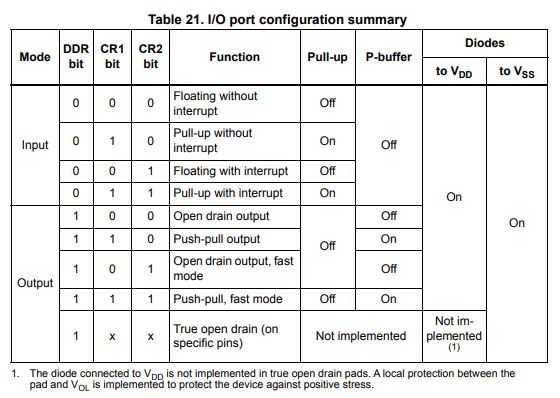
It would be nice to be able to set the pin as an input (with and without pull-up resistors) or as an output (push-pull or open drain). For now we won’t worry about interrupts and the fast mode. Then of course we need a way to read and set the state of the pins depending on their mode.
Writing the interface
Accessing the GPIO registers
As you remember the only way we have to interact with outside world is through the registers, which are mapped to specific address locations (from 0x005000 up to 0x0057FF):
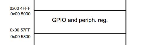
In the case of the STM8s003 or the STM8s103 the GPIO registers take from 0x005000 up to 0x00501D and they are grouped in ports. Each port is responsible of 8 GPIOs and contains 5 different registers to control them:
- Data Direction Register (DDR)
- Control Register (CR1 & CR2)
- Output Data Register (ODR)
- Input Data Register (IDR)
Note: Not all the registers are connected to exposed pins of the MCU.
Suddenly we have lots of things to take care of, but fortunately we start to distinguish a pattern:
all ports have the same types of register so we can group them somehow. In C we have the so called structs that allows us to group variables that have a relation between them. Probably you are already familiar with them, but in case you don’t, you can check out some of the many tutorials about the topic.
The struct feature we are mostly interested in is how they use the memory. If a struct is defined as packed (some compilers, like SDCC, do it by default) then the variables that belong to it are stored on after the other, without paddings. I recommend you to read this post: The Lost Art of Structure Packing. In essence, the struct becomes behaves similarly to an array, where we have a head pointer (that coincides with the 0th element), and the rest of the elements can be accessed sequentially. This is great, because we can map the port registers to a struct to get a more human-friendly access to them.
Last time, to access the value of a specific register we used a macro that dereferenced the physical address of that register like so:
#define PB_ODR *(volatile char*)0x5005
We still need the address of the registers, but now instead of defining each address individually we are only going to define the base address of each port. Notice that we only define the address and don’t dereference it, we will do that later on:
#define PA_BASE_ADDRESS     0x5000
#define PB_BASE_ADDRESS     0x5005
#define PC_BASE_ADDRESS     0x500A
#define PD_BASE_ADDRESS     0x500F
#define PE_BASE_ADDRESS     0x5014
#define PF_BASE_ADDRESS     0x5019
Now we are going to create the struct corresponding to the port. We are declaring it as a custom type, with the typedef tag, so we can create different ports afterwards:
typedef struct {
    uint8_t ODR;     // Port x output data register (Px_ODR)
    uint8_t IDR;     // Port x pin input register (Px_IDR)
    uint8_t DDR;     // Port x data direction register (Px_DDR)
    uint8_t CR1;     // Port x control register 1 (Px_CR1)
    uint8_t CR2;     // Port x control register 2 (Px_CR2)
} PORT_t;
Notice that the struct variables are all uint8_t, matching our microcontroller architecture. For example, if we were writing this code for a STM32 the variables should have been uint32_t.
Next comes the trickiest part, at least to me. We need to define a set of variables of type PORT_t that point to the base address of each port. This sounds trivial, but think for a moment how would you do it before continuing to read. The way of doing it is to create a pointer that points to the desired register location:
volatile PORT_t * PORT_A = (PORT_t*)PA_BASE_ADDRESS;
You can se we use the volatile keyword so that the compiler knows that the variable value stored in that specific memory location can change on its own and doesn’t try to optimize it.
In this other post about using C’s structs to access peripheral registers, the author also includes the const keyword in the declaration of the port handle:
volatile PORT_t * const PORT_A = (PORT_t*)PA_BASE_ADDRESS;
Wait a second… const? Isn’t this keyword used for constant elements? Well, indeed const is used for values but here we are not saying that the register value is going to be constant, rather that the address to which the pointer points to will remain constant, even if the value of the register changes. If you are interested in this topic this article explains it quite well.
There are other ways to declare the port handle, as a #define:
#define PORT_A (volatile PORT_t*)PA_BASE_ADDRESS
Or using SDCC’s special keyword __at(*address*), although this makes the code less portable:
volatile PORT_t __at(PA_BASE_ADDRESS) PORT_A;
In this last case the reference to the GPIO handle needs to be passed: foo(&PORT_A).
Let’s make a quick sketch see if all the alternatives work:
1
2
3
4
5
6
7
8
9
10
11
12
13
14
15
16
17
18
19
20
21
22
23
24
25
26
27
28
29
#include <stdint.h>

/* Port base address */
#define PA_BASE_ADDRESS         0x5000

/* Port registers */
typedef struct {
    uint8_t ODR;     // Port x output data register (Px_ODR)
    uint8_t IDR;     // Port x pin input register (Px_IDR)
    uint8_t DDR;     // Port x data direction register (Px_DDR)
    uint8_t CR1;     // Port x control register 1 (Px_CR1)
    uint8_t CR2;     // Port x control register 2 (Px_CR2)
} PORT_t;

volatile PORT_t * PORT_A_pointer = (PORT_t*)PA_BASE_ADDRESS;
volatile PORT_t * const PORT_A_pointer_const = (PORT_t*)PA_BASE_ADDRESS;
#define PORT_A_define (volatile PORT_t*)PA_BASE_ADDRESS
volatile PORT_t __at(PA_BASE_ADDRESS) PORT_A_using_at;

void foo(PORT_t * port){
    port->DDR = 0x01;
}

void main(){
    foo(PORT_A_pointer_const);
    foo(PORT_A_pointer);
    foo(PORT_A_define);
    foo(&PORT_A_using_at);
}
Executing the command below form the terminal compiles the sketch, and we see that it does so without throwing errors:
sdcc -mstm8 --out-fmt-ihx --std-sdcc11 main.c
Notice that foo()expects a pointer of type PORT_t, there are several reasons for that:
- It is more efficient to pass structs by reference, because only the address is needed. Otherwise, if passed by value, a copy of the whole struct needs to be created.
- If you think of it, it makes no sense to pass the struct by value as we want to modify the values held in specific registers.
- SDCC doesn’t allow structs to be passed by value.
Let’s compare the different alternatives first checking if and how the port handles are stored in memory:
                                8 ;----------------------------------
                                9 ; Public variables in this module
                               10 ;----------------------------------
                               11 	.globl _PORT_A_pointer_const
                               12 	.globl _main
                               13 	.globl _foo
                               14 	.globl _PORT_A_pointer
                               15 	.globl _PORT_A_using_at
                               16 ;----------------------------------
                               18 ;----------------------------------
                               19 	.area DATA
                    005000     20 _PORT_A_using_at	=	0x5000
                               21 ;----------------------------------
                               22 ; ram data
                               23 ;----------------------------------
                               24 	.area INITIALIZED
000001                         25 _PORT_A_pointer::
000001                         26 	.ds 2
                               27 ;-----------
...
...
008024                        135 _PORT_A_pointer_const:
008024 50 00                  136 	.dw #0x5000
                              137 	.area INITIALIZER
008026                        138 __xinit__PORT_A_pointer:
008026 50 00                  139 	.dw #0x5000
We see that the pointer alternative behaves as a normal initialized variable and uses RAM (line 14) and flash (line 139) whereas the const pointer uses only fash (line 136). The #define “doesn’t use” memory at all as the preprocessor just writes the value of the #define each time it is referenced. Finally, __at() although it seems that it uses RAM (line 20), the compiler treats it in a similar way as with #define.
Next let’s look at the main section of the program:
                              111 ;	main.c: 30: foo(PORT_A_pointer);
008030 3B 00 02         [ 1]  112 	push	_PORT_A_pointer+1
008033 3B 00 01         [ 1]  113 	push	_PORT_A_pointer+0
008036 CD 80 28         [ 4]  114 	call	_foo
008039 5B 02            [ 2]  115 	addw	sp, #2
                              116 ;	main.c: 31: foo(PORT_A_pointer_const);
00803B CE 80 24         [ 2]  117 	ldw	x, _PORT_A_pointer_const+0
00803E 89               [ 2]  118 	pushw	x
00803F CD 80 28         [ 4]  119 	call	_foo
008042 5B 02            [ 2]  120 	addw	sp, #2
                              121 ;	main.c: 32: foo(PORT_A_define);
008044 4B 00            [ 1]  122 	push	#0x00
008046 4B 50            [ 1]  123 	push	#0x50
008048 CD 80 28         [ 4]  124 	call	_foo
00804B 5B 02            [ 2]  125 	addw	sp, #2
                              126 ;	main.c: 33: foo(&PORT_A_using_at);
00804D 4B 00            [ 1]  127 	push	#<(_PORT_A_using_at + 0)
00804F 4B 50            [ 1]  128 	push	#((_PORT_A_using_at + 0) >> 8)
008051 CD 80 28         [ 4]  129 	call	_foo
008054 5B 02            [ 2]  130 	addw	sp, #2
The call to foo is the same each time, but pushing the argument value to stack is done differently. The main parameters to take into account while comparing the alternatives are: number of instructions, length of the instructions and the number of cycles each instruction requires.
| Alternative | Line nº | Mnemonic | Hex | Length | Cycles |
|---|---|---|---|---|---|
| Pointer | 112 | push | 3B 00 02 | 3 | 1 |
| 113 | push | 3B 00 01 | 3 | 1 | |
| Const Ptr | 117 | ldw | CE 80 24 | 3 | 2 |
| 118 | pushw | 89 | 1 | 2 | |
| Define | 122 | push | 4B 00 | 2 | 1 |
| 123 | push | 4B 50 | 2 | 1 | |
| __at() | 127 | push | 4B 00 | 2 | 1 |
| 128 | push | 4B 50 | 2 | 1 |
This comparison is not 100% valid, as depending on the C code the assembly can be generated differently even if using the same port handle, nevertheless it seems that for us the #define alternative does a better job, with a faster and smaller code.
Next, we add the handles for the remaining ports using the #define method ending up with a code that looks like follows:
/* Port base address */
#define PA_BASE_ADDRESS         0x5000
#define PB_BASE_ADDRESS         0x5005
#define PC_BASE_ADDRESS         0x500A
#define PD_BASE_ADDRESS         0x500F
#define PE_BASE_ADDRESS         0x5014
#define PF_BASE_ADDRESS         0x5019

/* Port registers */
typedef struct {
    uint8_t ODR;     // Port x output data register (Px_ODR)
    uint8_t IDR;     // Port x pin input register (Px_IDR)
    uint8_t DDR;     // Port x data direction register (Px_DDR)
    uint8_t CR1;     // Port x control register 1 (Px_CR1)
    uint8_t CR2;     // Port x control register 2 (Px_CR2)
} PORT_t;

/* Port handles */
#define PORT_A (volatile PORT_t*)PA_BASE_ADDRESS
#define PORT_B (volatile PORT_t*)PB_BASE_ADDRESS
#define PORT_C (volatile PORT_t*)PC_BASE_ADDRESS
#define PORT_D (volatile PORT_t*)PD_BASE_ADDRESS
#define PORT_E (volatile PORT_t*)PE_BASE_ADDRESS
#define PORT_F (volatile PORT_t*)PF_BASE_ADDRESS
Finally, let’s create an enumeration to group all the possible pins in a port:
/* Pins */
typedef enum { PIN_0, PIN_1, PIN_2, PIN_3, PIN_4, PIN_5, PIN_6, PIN_7 } PIN_t;
Now we have a way to reference all the GPIO using their port and pin.
Adding helper functions
In our previous blink code we manipulated the GPIO manually using bitwise operations over the GPIO registers directly. We cannot change much about that, but we can create a set of small functions that make our code much more readable and less repetitive.
/* Pin modes */
typedef enum { INPUT, INPUT_PULLUP, OUTPUT, OUTPUT_OPEN_DRAIN } GPIO_MODE_t;

void gpio_set_mode(PORT_t *port, PIN_t pin, GPIO_MODE_t mode) {
    switch(mode){
        case INPUT:
            port->DDR &= ~(1 << pin);
            port->CR1 &= ~(1 << pin);
            break;
        case INPUT_PULLUP:
            port->DDR &= ~(1 << pin);
            port->CR1 |= (1 << pin);
            break;
        case OUTPUT_OPEN_DRAIN:
            port->DDR |= (1 << pin);
            port->CR1 &= ~(1 << pin);
            break;
        case OUTPUT:
            port->DDR |= (1 << pin);
            port->CR1 |= (1 << pin);
            break;
    }
}

void gpio_write(POR_t port, PIN_t pin, bool value) {
    value ? port->ODR |= (1 << pin) : port->ODR &= ~(1 << pin);
}

void gpio_toggle(PORT_t port, PIN_t pin){
    port ^= (1 << pin);
}

bool gpio_read(PORT_t port, PIN_t pin){
    return (port->IDR & (1 << pin) > 0) ? true : false;
}
Testing the interface
Let’s test our brand new interface rewriting the blink example:
1
2
3
4
5
6
7
8
9
10
11
12
13
14
15
16
17
18
19
20
21
22
23
24
25
26
27
28
29
30
31
32
33
34
35
36
37
38
39
40
41
42
43
44
45
46
47
48
49
50
51
52
53
54
55
56
57
58
59
60
61
62
63
64
65
66
67
68
69
70
71
72
73
74
75
76
77
78
#include <stdint.h>
#include <stdbool.h>

/* Port base address */
#define PA_BASE_ADDRESS         0x5000
#define PB_BASE_ADDRESS         0x5005
#define PC_BASE_ADDRESS         0x500A
#define PD_BASE_ADDRESS         0x500F
#define PE_BASE_ADDRESS         0x5014
#define PF_BASE_ADDRESS         0x5019

/* Port registers */
typedef struct {
    uint8_t ODR;     // Port x output data register (Px_ODR)
    uint8_t IDR;     // Port x pin input register (Px_IDR)
    uint8_t DDR;     // Port x data direction register (Px_DDR)
    uint8_t CR1;     // Port x control register 1 (Px_CR1)
    uint8_t CR2;     // Port x control register 2 (Px_CR2)
} PORT_t;

/* Port handles */
#define PORT_A (volatile PORT_t*)PA_BASE_ADDRESS
#define PORT_B (volatile PORT_t*)PB_BASE_ADDRESS
#define PORT_C (volatile PORT_t*)PC_BASE_ADDRESS
#define PORT_D (volatile PORT_t*)PD_BASE_ADDRESS
#define PORT_E (volatile PORT_t*)PE_BASE_ADDRESS
#define PORT_F (volatile PORT_t*)PF_BASE_ADDRESS

/* Pins */
typedef enum { PIN_0, PIN_1, PIN_2, PIN_3, PIN_4, PIN_5, PIN_6, PIN_7 } PIN_t;

/* Pin modes */
typedef enum { INPUT, INPUT_PULLUP, OUTPUT, OUTPUT_OPEN_DRAIN } GPIO_MODE_t;

void gpio_set_mode(PORT_t *port, PIN_t pin, GPIO_MODE_t mode) {
    switch(mode){
        case INPUT:
            port->DDR &= ~(1 << pin);
            port->CR1 &= ~(1 << pin);
            break;
        case INPUT_PULLUP:
            port->DDR &= ~(1 << pin);
            port->CR1 |= (1 << pin);
            break;
        case OUTPUT_OPEN_DRAIN:
            port->DDR |= (1 << pin);
            port->CR1 &= ~(1 << pin);
            break;
        case OUTPUT:
            port->DDR |= (1 << pin);
            port->CR1 |= (1 << pin);
            break;
    }
}

void gpio_write(PORT_t *port, PIN_t pin, bool value) {
    if(value)
        port->ODR |= (1 << pin);
    else
        port->ODR &= ~(1 << pin);
}

void gpio_toggle(PORT_t *port, PIN_t pin) {
    port->ODR ^= (1 << pin);
}

bool gpio_read(PORT_t *port, PIN_t pin) {
    return (port->IDR & (1 << pin) > 0) ? true : false;
}

void main(){
    gpio_set_mode(PORT_B, PIN_5, OUTPUT_OPEN_DRAIN);

    while(1){
        gpio_toggle(PORT_B, PIN_5);
        for(int i = 0; i < 30000; i++){;}
    }
}
And that’s it! Our LED should be blinking as good as before, but now it is easier to read and maintain the code.
#define HELLO 10

int main (){
    return 0;
}