When learning how to work with a new target the first step is always the hardest: setting up the development environment. Many times this is overlooked, but I would like to go step by step and show what tools are required and how to install them in your preferred OS.
You will often find that tutorials rely on you using some sort of Linux flavour or MacOS. I see the point, sometimes it is just… easier. But I think is fine to get the most of the tools you have in order to learn, letting other criteria aside.
When I was starting with STM8 microntrollers myself I stumbled upon this exquisite tutorial from Lujji. These articles inspired on that tutorial and are intended to complement it. Although the author was using some tools for Unix it was really easy to comprehend what tools were needed. The approach of using independent tools for writing, compiling and flashing allows understand better what is happening at the different stages of programming the microcontrollers.
The hardware
We have plenty of options to choose from for our hardware, from Dev boards to bare MCUs. I went for the so called STM8 blue. This is a cheap dev board built around the STM8S003F3P6 or STM8S103F3P6, a value line 8-bit microcontroller with the following specs:
- 8 KByte of flash memory
- 1 KByte of RAM
- 128 Bytes of EEPROM
- Hardware I2C, UART & SPI
- 10 bit ADC
- 16 GPIOs
The board has few extra components such as a ASM1117 3.3V regulator, power and user LEDs and a reset button. More information about the board can be found here.
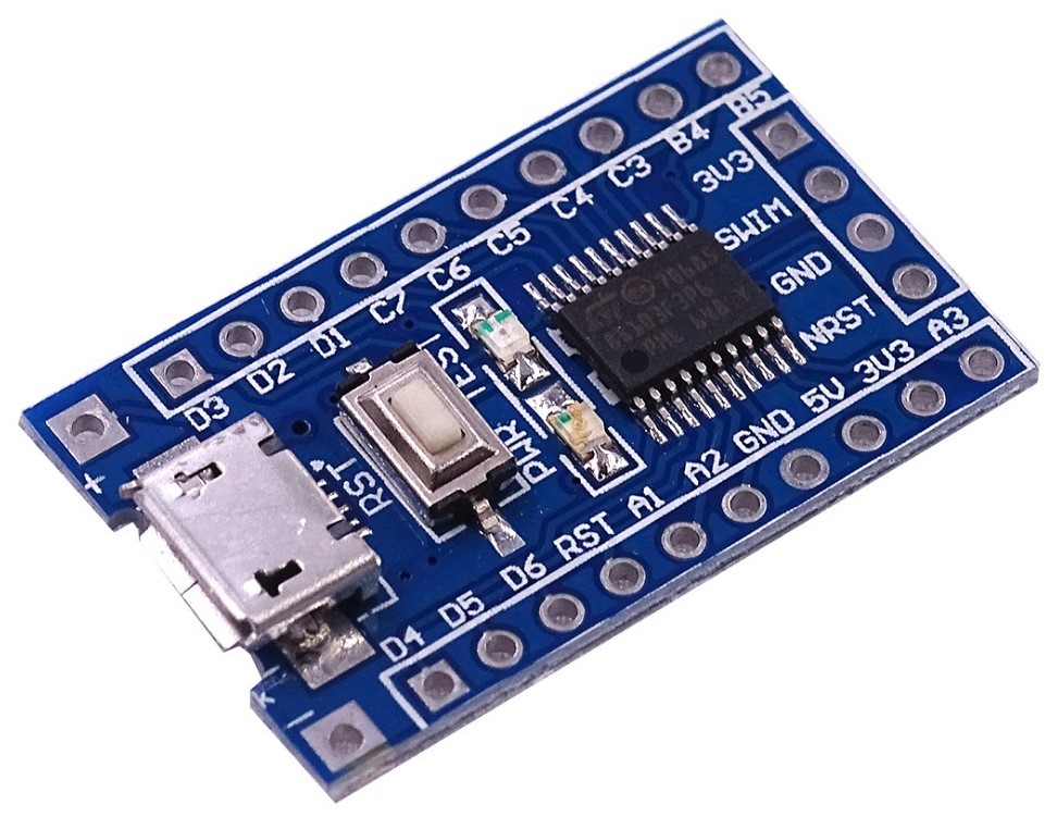
Note: Note the STM8S003F3P6 it is only guaranteed to work for up to 100 flash cycles (although I probably flashed it more times than that). If you need to buy one I suggest you to get the STM8S103F3P6 instead, it supports up to 10000 flash cycles.
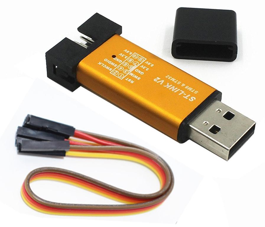
The microcontroller will be programmed with a flashing device, in this case a clone ST-LINK V2:
The software
To start developing we will need: a text editor, a toolchain and a flashing tool.
Any text editor will do, so choose the one you like the most (I’m using Visual Studio Code).
We will be using the C programming language, so next we need to install a suitable toolchain for building our firmware. There are several options but we are going to use SDCC, which is a free open source compiler suite for many embedded targets, including our beloved STM8. The homepage can be found here.
Go to the downloads page and get the latest installer. Execute it and follow the instalation steps. Once the tool is installed add it to Windows PATH. If you don't know how to do it follow this tutorial. The default binary directory is: C:\Program Files\SDCC\bin.
Open a terminal and run:
sudo apt install sdccOpen a terminal and run:
sudo apt install sdccOpen a terminal and run:
brew install sdccIf everything went well, you should be able to check the SDCC version typing:
sdcc --version
Finally we need a a flash tool, which is necessary to load the compiled binaries to the desired target.
ST Visual Programmer is the official ST tool for flashing devices and comes with a Graphical User Interface (GUI) as well as with a Command Line Tool. It can be downloaded from here, you might be asked to provide your email when downloading. Be sure to add the folder that contains the CLI to the PATH, and verify the installation typing:
STVP_CmdLine -versionThere is no support for USB devices on WSL (apart from USB drives and USB to Serial Converters in WSL1). Fortunately, Windows commands can be invoked from WSL as well, so just install it for Windows and verify the installation from a WSL terminal typing (notice the ".exe"):
STVP_CmdLine.exe -versionstm8flash
stm8flash
Cool! We have successfully installed all the necessary software and we are ready to do some STM8 programming.
Bare metal programming
As mentioned before, we will be writing our firmware in C. We will start programming without any libraries, having to directly interact with the hardware of the microcontroller, so it is good idea to keep a copy of the Datasheet and the Reference Manual on hand during the reading.
Inside a microcontroller memory is organized in blocks, commonly know as registers, where information can be stored, each of this blocks is identified by an address:
| Address | Value |
|---|---|
| 0x00 | 0xFF |
| 0x01 | 0x00 |
| 0x02 | 0x0A |
By accessing a specific address its contents can be read or modified. In order to do so we need to use pointers. A pointer is a coding element that stores the address of a register in its value field, essentially it points to its address. Pointers can also be dereferenced to access the values stored in that register, e.g.
int var = 0xD3;  // We store 0xD3 in "var"
int *ptr = &var; // We store the address of "var" in "ptr"
*ptr = 0x0C;     // We dereference "ptr" and update the value of "var" to 0x0C
When programming we don’t usually know what memory addresses are used, and we don’t really care as long as everything is inside the proper boundaries. However, to interact with the hardware we actually need to know “some” specific memory addresses to access the so called Special Function Registers (SFR). This registers are presented in the datasheet and explained in detail in the reference manual.
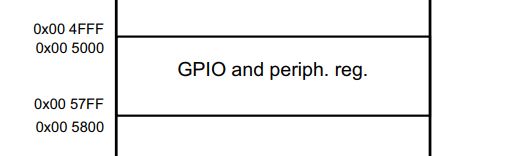
In the page 30 of our target microcontroller’s datasheet the memory map is shown, and we
can see that the SFR addresses for GPIO and peripherals go from 0x005000 up to 0x0057FF:
In the next pages, we can see a list of the different registers and their addresses and a summary of their purpose. In the reference manual, a more detailed explanation can be found about each one.
For different examples the same procedure will be followed to write to code:
- Identify the hardware
- Look in the datasheet and ref. manual for the proper register addresses
- Write the firmware
Blinking an LED
For our first program we are going to flash the built-in LED on the STM8 blue pill. In the image below the pinout of the breakout board is showed:
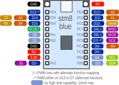
The built-in LED is connected to 3v3 and to the fifth pin of the Port B (PB5) so pulling the pin low will turn the LED on.
Based on the electrical layout of our board, now we can figure out what registers we need to use. Microcontrollers often have what are called General Purpose Inputs Outputs (GPIO) that can implement many different functions as shown in the datasheet (page 25), but for now we will only focus on using them as digital inputs and outputs.

GPIO have various configuration options that can be set through these registers:
- Data Direction Register (DDR)
- Control Register (CR1 & CR2)
- Output Data Register (ODR)
- Input Data Register (IDR)
We need to setup PB5 as an open drain output. In the reference manual (page 107) all the possible configurations are presented:
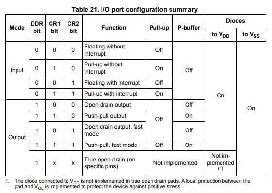
We just have to set to 1 the proper DDR bit, because PB5 only supports open drain mode as an output.
Checking again the datasheet (page 31) and the reference manual (page 111) we can find the addresses for the necessary registers:
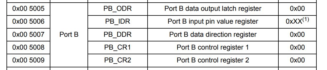
The addresses we are interested in are 0x005000 for ODR and 0x005007 for DDR.
The code
To start with, we need to create a main.c file with the code shown below. I suggest keeping the files organized and using on folder per example. The code for this tutorials is available on Github.
1
2
3
4
5
6
7
8
9
10
11
12
13
#define PB_ODR *(volatile char*)0x5005
#define PB_DDR *(volatile char*)0x5007

void main() {

  PB_DDR = (1 << 5);

  while(1) {
    PB_ODR ^= (1 << 5);
    for(int i = 0; i < 30000; i++){;}
  }

}
Let’s analyze the code line by line. The first thing we do is create a macro to easily access the contents of the required registers. We are casting the addresses, stored as a literal, to a pointer of type volatile char and then dereferencing that pointer to access the data. We cannot directly dereference literals.
#define PB_ODR *(volatile char*)0x5005
#define PB_DDR *(volatile char*)0x5007
The keyword volatile indicates the compiler to not optimize that element, this is necessary because the SFR may change during run time by unknown source
(not known to compiler). Check this for more information. Also notice that we are not defining any variable, for instance, whenever we use PB_ODR we are actually copying *(volatile char*)0x5005.
Note: The char type signedness generally depends on the compiler specification. In this case, there is no sense in using the signed version as we are dealing only with GPIO registers, however we don’t need to add the unsigned tag as by default SDCC treats char as an unsigned type. More can be found in the SDCC user guide (page 8).
Inside the main function we configure the PB_DDR to set PB5 as an output.
PB_DDR = (1 << 5); // Or 0b00100000 or 0x20
Next, we implement and infinite loop where we periodically toggle the LED pin using bitwise operations. The delay is created using a long for loop with nothing inside.
while(1) {
  PB_ODR ^= (1 << 5);
  for(int i = 0; i < 30000; i++){;} // Basic delay
}
Compiling the code
To compile the code we are going to use the SDCC from the Command Line Interface. Open a terminal and navigate to the folder that contains your main.c file using cd and dir commands. Tip: How to navigate in CMD. Now execute the following command to start the compilation:
sdcc -mstm8 --out-fmt-ihx --std-sdcc11 main.c
Let’s analyze the different parts:
- -mstm8 define the microcontroller (stm8)
- –out-fmt-ihx define the compiled file format (.ihx)
- –std-sdcc11 follow the C11 standard but allow some conflicts
- main.c the file to be compiled
Note: More information about the compilation options can be found executing sdcc --help or reading the SDCC user guide (starting from page 26).
A few files will be generated after the compiler has done its job. For now we are mostly interested in the main.ihx file. The extension .ihx stands for Intel Hex and it contains the compiled firmware that we need to upload to the microcontroller. If you need need a .hex file, SDCC comes with a tool to convert .ihx to .hex:
packihx main.ihx > main.hex
Flashing the firmware
Now it is time to flash our device and the first thing we need to do is to connect the STM8S blue pill to the ST-Link. We are going to use the SWIM protocol that requires only one data line. The connections will be the following:
| ST-LINK | STM8 Board |
|---|---|
| GND | GND |
| 3.3V | 3.3V |
| SWIM | SWIM |
| RST | RST |
The next step is to load the firmware to the target. Depending on the OS we are using we will have different alternatives.
If you are using windows we have two options, either use the GUI or the Command Line Tool.
Using the STVP GUI
Start the GUI and go to Configure -> Configure ST Visual Programmer, then select ST-LINK as Hardware, SWIM as Port, and your microcontroller model in Device, in my case STM8S003F3. Next go to File -> Open... and select the .hex file and finally go to Program and press Current Tab. At this point the build-in LED of your board should start blinking.
Using the STVP_CmdLine
Open the CMD and again make sure that you are in the project folder, then execute:STVP_CmdLine -Device=STM8S003F3 -no_log -no_loop -FileProg=main.ihxOpen a terminal and run (Notice the .exe):
STVP_CmdLine.exe -Device=STM8S003F3 -no_log -no_loop -FileProg=main.ihxIf you are using stm8flash, you can simply call:
stm8flash -c stlinkv2 -p stm8s003f3 -w main.ihxIf you are using stm8flash, you can simply call:
stm8flash -c stlinkv2 -p stm8s003f3 -w main.ihxAnd that is it! You should have your LED flashing.